USER INTERFACE
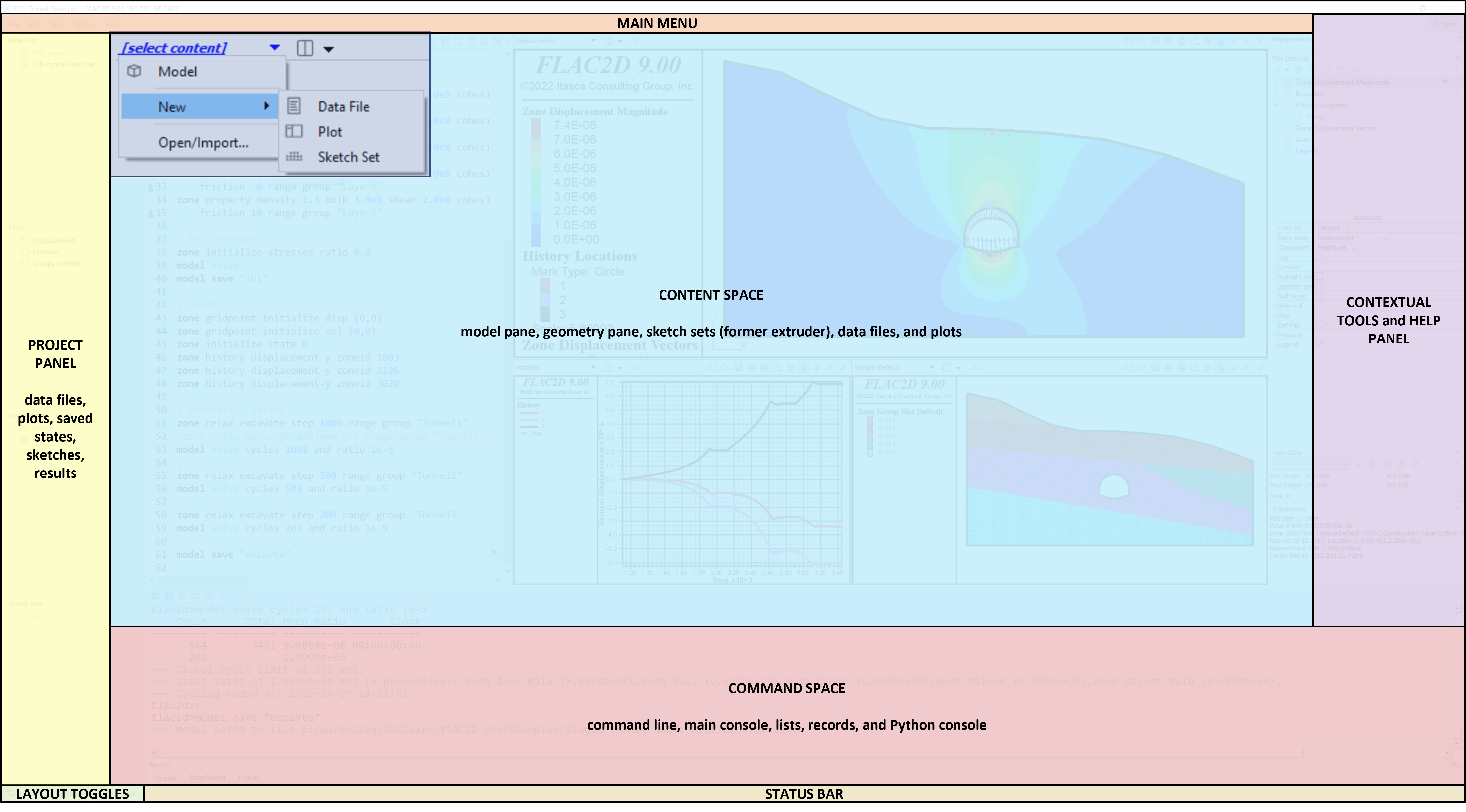
FLAC2D features the improved user interface (UI) of Itasca's Version 9 software. The UI consists of the Main Menu; the Project pane to view associated files and plots; the Command Console to input or view model commands and see model output or program messages (information/warnings/errors); the Content Workspace for creating new, and editing existing data files, plots, sketch sets, and the Model pane; the Contextual Tools/Help panel which changes depending on what has focus; the Layout Toggles to hide and show the the Project pane, Workspace, or Command Console; and the Status bar.
Use the Content Selector (the drop-down menu above the Content Workspace) to create plots, data files, sketch sets, or the work in the Model Pane. Then use the split icon (rectangle with a vertical line) to create new content to the left or right, or above or below the existing tile. This can be repeated for several levels of splitting. You may also double-click on certain file types listed in the Project Panel to bring them into the current tile. Each tile has it's own contextual tool bar. Easily manage your data files, sketch sets, saved model states, and hundreds of plots for working on real projects. Tiles can be closed by using X icon. This layout is saved with the Project.
Model execution (green arrow icon) and stop (red stop sign icon) now resides within the Text Editor and each data file making up the model.
SKETCH Workspace
The Sketch workspace provides interactive tools for drawing and meshing 2D models. A sketch is a 2D geometric design of a model that can be created interactively. For FLAC2D, zones are directly created from a sketched design (termed a set). Each “sketch” is created within a separate sketch set; a modeling project may contain multiple sets.
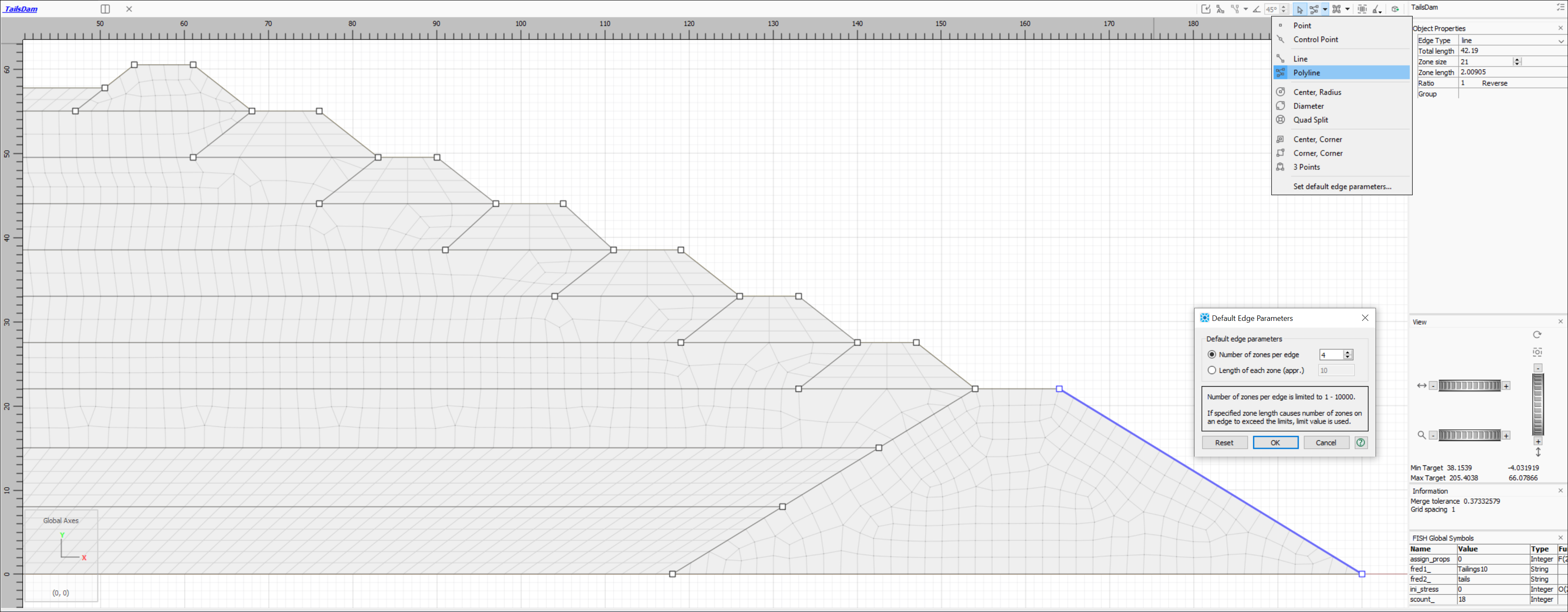
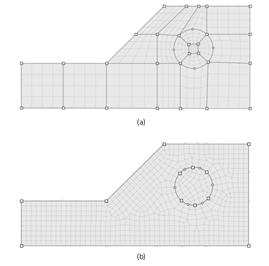
Both (a) structured and (b) unstructured meshes may be automatically generated in the Sketch workspace. Any closed (watertight) polygon can be meshed. Structured mesh can be used only for simply-connected 3- or 4-sided polygons, while unstructured mesh can be applied to any closed polygon.
Operations in the Sketch workspace are automatically translated into commands that are sent to the Console pane. You can save or copy the record of these operations to help learn the actual commands, to reproduce the sketch set exactly, or to use as a starting point for parameterizing the sketch.
MODEL PANE
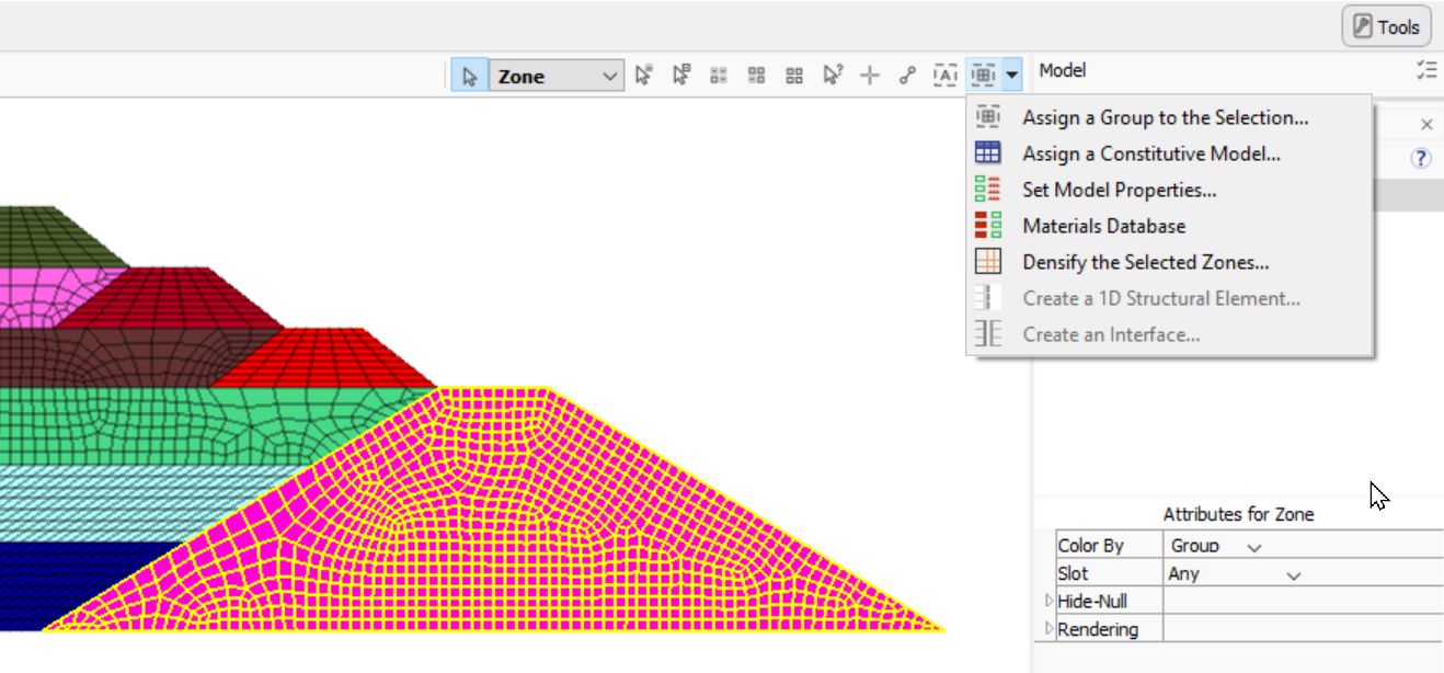
The Model pane is an interactive user interface for displaying the current model. It has tools for selecting, showing, hiding, and grouping objects. As you manipulate your model, most of your actions will be automatically translated into commands that are sent to the Console pane. There are a few tools specific to certain data sets (zones, beam, pile, cable, and zone faces/edges) via the drop-down menu:
ZONES
- Assigning a Group Name to a Selection
- Assigning a Constitutive Model
- Set Model Properties
- Access the Materials Database
- Densify Selected Zones
- Set Color Labels
ZONE FACES/EDGES
Automatically "skin" the model to generate face/edge groups. “Skinning” refers to automatic face group generation, which occurs as follows: the program looks for contiguous faces on the boundaries of zone blocks and puts them into automatically named groups within the slot named Skin. Two faces are not considered contiguous if: the angle between two faces exceeds the break-angle, or if the two faces belong to different groups. Unless internal is specified, the operation of the command is restricted to external faces. This is very useful for defining the model boundaries and easily assigning boundary conditions.
TEXT EDITOR
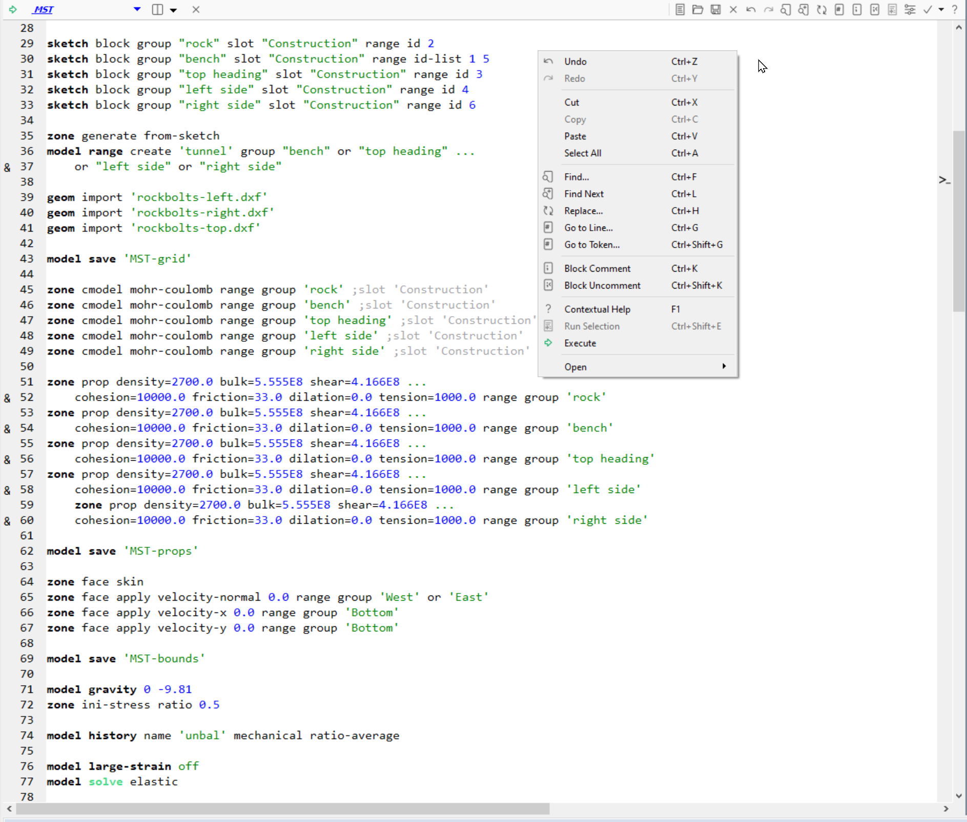
The built-in Text Editor provides the ability to edit text-based project resources (data files, FISH files, etc.). It is limited to the display of text and may be used with any text file, including Python scripts (providing these are saved as *.py files). The main tools for text editing appear on the the toolbar, most of which also appear on the pane’s right-click menu. Users may customize preferences and settings.
The Text Editor provides features specifically designed to work with Itasca software data files, including: automatic syntax highlighting; collapsible FISH blocks, commenting/uncommenting lines, line numbering, and command-authoring assistance tools. Perhaps most importantly, command processing of a data file’s contents is available from within the pane via the “Execute/Stop” button ( run ) on the toolbar. One or more lines of code may be executed using “Run Selection” button on the toolbar (or via the CTRL-SHIFT-E keyboard shortcut).
CONSTITUTIVE MODELS
- FLAC2D includes 23 built-in constitutive models:
- Null
- Elastic
- Anisotropic Elastic
- Druker-Prager
- Mohr-Coulumb
- Ubiquitous-Joint
- Ubiquitous-Anisotropic
- Strain-Softening/Hardening
- Double-Yield
- Modified Cam-Clay
- Swell
- Bilinear Strain-Softening/Hardening Ubiquitous-Joint
- Hoek-Brown
- Hoek-Brown-PAC
- CYSoil
- CHSoil
- Plastic-Hardening
- Soft-Soil
- Finn
- NorSand
- P2PSand
- Von-Mises
- Concrete
